Product Categories
Manufacturers Worldwide Delivery


Case Studies
Mark Barmby First Visit - my objective was to get the Victron 48V, 3000VA MultiPlus inverter/charger running. As the battery was a BYD system, there was a 48V, 50Ah unit connected to a battery management unit (BMU).
Mark Barmby
First Visit
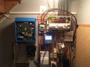
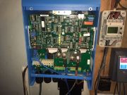
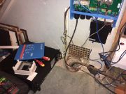
When we first arrived, my objective was to get the Victron 48V, 3000VA MultiPlus inverter/charger running. As the battery was a BYD system, there was a 48V, 50Ah unit connected to a battery management unit (BMU). The BMU is in control of monitoring the battery and making sure it is healthy. For the BMU to work through the Multi, there is a CAN type A cable that is required which has specific pins in use to make the BMU talk with the Color control panel.
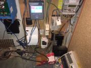
The cable that was in use when we arrived was a standard ethernet cable which would not be adequate. We put in place the correct cable that we brought with us and attempted to turn on the Multi, it would switch on for a few seconds and then switch off. The color control would display a warning that the battery voltage is too low, showing 45.50V. To try and charge the battery up from the mains I changed the ESS settings in the Color control to force it to charge the battery from the mains. I tried to switch on again, but it did not charge and switched off. At this stage I thought that the mains connection might not be adequate, the mains connection went into the containment of the installed ET340 energy meter. After I removed the cover, I could see the issue straight away, the Multi AC connection was not connected correctly to anything. The customer had mentioned previously that the original installer had issues with the battery not charging and after 4 visits he was unable to source the problem. With this knowledge, I assumed that the installer gave up on the system and just connected the solar to the distribution board and avoided the ET340 entirely. To provide the Multi with an AC connection, we wired a plug onto the end of the cable and used a nearby plug socket. With the new connection in place I turned on the Multi and the battery began to start charging, at this stage we took a few minutes break to let the battery charge up to 95% state of charge (SOC). After returning with the Multi switched I wanted to get into it and check that the programming was correctly instated by the previous installer. The normal process for this is to use a MK3 RJ45 to USB converter and plug our laptop into the Multi. I attempted this using the spare RJ45 VE Bus port in the Multi, I turned off the Multi put in the cable and tried to restart the Multi. The Multi would not switch back on, I tried turning off the mains connection but was still unsuccessful. In an attempt to get around this issue, I remembered that there was a relatively new feature on the Victron Remote Management (VRM) site.
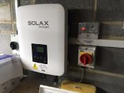
Through the VRM I was able to download the Multi settings, update them and the upload the new settings. As the previous installer did not get to this point, I had to put the installation onto the VRM from the beginning by putting in the VRM portal ID. This was good in a way as we received full access and was able to change the settings that we needed. Before doing this, we had to put in a nano USB Wi-Fi dongle and enter the customers Wi-Fi password. Once the Wi-Fi was setup, I enabled all the settings on the Color control, such as remote console, two-way communication and other small settings. Once the VRM was setup I made sure everything was working and moved onto using the remote VE config. I downloaded the settings and referring to the Victron manuals for BYD integration I changed the required settings and updated the ESS assistant. I then saved the settings and attempted to upload them; this did not work. The VRM can only accept .VRSC files and the file type that I had was a. vsc after saving the settings. As I had not run into this problem and as time was getting on a bit, we left this problem to research further when back in the office. After this, we looked into wiring up the ET340 energy meter correctly and what would be involved. For this meter to work correctly, I should have the main tails from the supply going through it and the solar supply going through. The solar inverter was located in the garage on the other side of the house; however, the previous installer had provided a steel wire armor (SWA) 3-core cable that ran from the inverter to the meter. After inspecting the solar inverter in the garage, the inverter went through the AC switch, generation meter and then was connected to the SWA cable in a nearby distribution board. Knowing this, we knew that the other end of the SWA cable could be treated as the solar supply and at that time was connected with WAGO clamps to another cable that was in a 16A MCB in the distribution board near the supply. With these cables in place we only needed to route the main tails through the ET340 and reroute the SWA cable.
At this stage the time was around 5:30pm and as we had a 3-4-hour drive ahead we spoke with the customer about the above issues and we said we will research the VRM issue and get some tails ready to finish the job. We went back to the office and when I had a spare hour, I looked into the VRM issue, I looked up if any manuals would help and was stuck for a little while. The remote VE configure section had a video, after viewing it turned out that the correct process was to save the file and then open it. When I was on site, I was opening the file and then saving, this would produce a .vsc file. By saving the file first it becomes a. rvsc and I used our little setup in the office to test this. I went on our VRM, downloaded the settings, saved them and changed them. When I went to download, I could see that it was indeed a .rvsc file and successfully uploaded them. With this new knowledge and having bought the tails we were ready to return to the job.
Second Visit
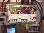
We left early to hopefully beat the traffic there and, on the way, back. When we arrived, I updated the Multi settings through the VRM using the process above. We then started the wiring of the ET340 right away. I wired up the solar side, the Multi and the connection to the distribution board. I used a couple of WAGO clips to keep all the earth cables together and the neutral cables together. The solar fed through the ET340 and then went out into the distribution board, the Multi took a positive feed from the solar out. At this stage I was not sure which cable should be used for the negative terminal on the ET340, we tried with the distribution board cable to start. After I was finished Colin turned off the power and removed the main fuse to start work on the tails. We routed where the main positive tail comes out and goes into another Henley block, we then took the tail and routed it through the ET340 and used our new length to reconnect it to the Henley block. Once all was connected, we turned back on the power to test the ET340, after switching on the MCB that the board was using to connect, the RCD would trip. This would happen instantly and every time we tried with this setup. We tried using a different neutral cable that we had, but this would still trip. As the inverter, board and Multi required a neutral connection we stripped a twin and earth cable and used a section of the neutral cable to connect the board to the ET340. Using this still tripped the RCD. Based on our previous experience of the ET340 causing problems on another system, we changed it out to an EM24 meter. We turned off the power and inserted all of the cables, when trying again the RCD was still tripping. At this stage we were unsure as to why it was tripping, so we checked the inverter side distribution board to check all cable paths and was confident it was wired as it should. Without any further progress we called the Carlo Gavazzi technical helpline, the man we spoke with explained the wiring of the EM24 and its function. He mentioned that the neutral terminal is just used a reference point and does not need to be from a circuit, this confirmed that our extra neutral cable should have been used. So, our wiring was correct, but the RCD was still tripping, the helpline contact explained why the RCD would trip and came to the conclusion that there must be a fault in the system. With this knowledge we tried a different MCB in the board, it still tripped, we used a new length of cable to connect the EM24 to the board and it still tripped. I remembered that at one stage we managed to get some success, but the solar neutral was not connected to anything, this meant that the fault must be down the solar inverter side. To test this theory further we went into the garage and wired the inverter straight into and MCB at the nearby distribution board. This meant that the solar was isolated to just the board and equipment. When we switched on the MCB the inverter switched on and confirmed that the problem was not to do with the inverter or board. We then tested if the SWA cable was at fault by leaving the cables in the EM24 and disconnecting them at the other end to check if the RCD would still trip, when we tested the RCD didn’t trip. This confirmed that the SWA cable was fine and the only problem could be the board near the main supply, this was reassured because they had a lighting circuit which was moved on the other side of the RCDs, we assume this was due to nuisance tripping which could also indicate a fault. To avoid this board entirely, we used the SWA to extend the solar supply through the EM24 and used the grey earth cable as the positive return to the board and wired that into the MCB into the inverter board.
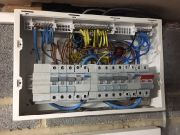
The neutral cable from the SWA was used to connect the inverter board to the EM24, this worked because the inverter board was fed from the main supply, but separately to the other board. With this setup we switched on and the solar and EM24 worked as expected. The next problem was getting the Multi switched on and reading the values from the EM24, these values are passed through an RS485 to USB cable which is connected to the color control which will display if this cable is working or not. At this stage the EM24 was not displayed on the color control and so we looked into the cable connection. Using the Victron manual for BYD we needed to use the yellow, orange and black cable on the RS485 side in that order in the EM24 data ports. We moved the cables into the correct ports and reconnected the USB into the color control and the EM24 came up on the color control. From there we went into the energy meter settings in the color control and setup the EM24 as a single-phase grid meter with the solar on phase 2. After this was all setup, we tried to switch on the Multi but heard some contact issues for the plug as we only temporarily wired one up. We removed the plug and cable and cut a new length of cable and wired in a new plug, we connected this up to the Multi and it worked well. At this stage with everything working as it should I looked into the color control settings and made sure everything is correct, so ESS was using optimized without battery life, it was a single phase system and I setup charging on Monday mornings to keep the battery healthy. Once all that was satisfactory, we put the covers back on everything and cleared up the workspace. We spoke with the customer, explained our solutions and that we will continue to monitor the system using the VRM.
01708 223733 Colin or Jacques